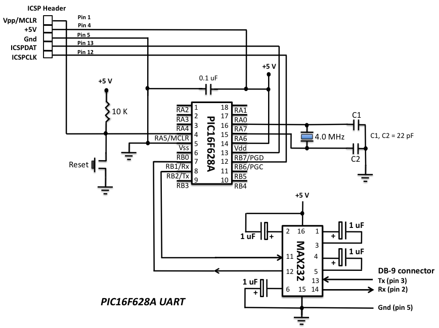
Download schematic in PDF Circuit Description. The heart of the LED chaser is the PIC 16F628A microcontroller, IC2. The program that runs on this. Welcome to Double Driver. One of the main reasons why you would want to collect installed drivers is if you don’t have the. Short Description. PICs are single-chip microcontrollers which can be used for many purposes. WinPic can program some of these devices, using a simple piece of. PWM Pulse Width Modulation is a technique used to generate analog signals from digital signals. Most of the PIC Microcontrollers have built-in PWM modules. How to burn or program PIC Microcontroller? Gallery of Electronic Circuits and projects, providing lot of DIY circuit diagrams, Robotics & Microcontroller Projects.
Electronics- DIY. Downloads. Win. PIC Programmer. It supports JDM, JDM PIC- programmer 2, Velleman K8. Hoodmicro, programmer and can program the following microcontrollers. PIC3. 0F2. 01. 0 (theoretically ALL ds.
PIC3. 0F devices supported, a few tested). PIC1. 6C6. 1, PIC1. C7. 1. # PIC1. 6C8. PIC1. 6F8. 4. # PIC1. C7. 10, PIC1. 6C7.
PIC1. 6C7. 15. # PIC1. F2. 00, PIC1. 0F2.

PIC1. 0F2. 04, PIC1. F2. 06. # PIC1. 2F6. PIC1. 2F6. 35, PIC1. F6. 75, PIC1. 2F6. PIC1. 2F6. 09, PIC1. F6. 10, PIC1. 2F6. PIC1. 6F6. 16 (new since 2.
PIC1. 6F6. 27, PIC1. F6. 27. A, PIC1. 6F6. PIC1. 6F6. 28. A. PIC1. 6F6. 30, PIC1. F6. 36, PIC1. 6F6. A. # PIC1. 6F6. 76, PIC1. F6. 84, PIC1. 6F6.
PIC1. 6F7. 3, PIC1. F7. 37, PIC1. 6F7. PIC1. 6F7. 6, PIC1. F7. 7. # PIC1. 6F8. PIC1. 6F8. 19. # PIC1.
March 25, 2005. If you log onto the Kit Forum you will see Bob Axtell is hard at work redesigning MicroPro, and doing a new PIC ProgrammerKit 185.
F8. 7, PIC1. 6F8. PIC1. 6F8. 73. A.. PIC1. 6F8. 77. A. PIC1. 8F2. 42, PIC1. F2. 48, PIC1. 8F2. PIC1. 8F2. 58. # PIC1. F4. 42, PIC1. 8F4.
PIC1. 8F4. 52, PIC1. F4. 58. # PIC1. 8F2. XX0/2. XX5/4. XX0/4. XX5 (tested: PIC1.
16f628a Simple Programming
ZRLCAn impedance meter with auto- BIAS. I've been working on this project from over a year, and I think will be.

16f628a Simple Program In C#
As matter of fact, the program is ready and I'm very. I'm strongly convinced that nobody could really.
There are a lot of options in ZRLC meter. Is very difficult for me to explain. I 'm writing an exhaustive document for that purpose. In. this page I'll give the only very basic information, just for a first start. And a lot of other things. Be patient if for now if.
I'll be a little bit cryptic. The keyword is still the same: time! A little preamble. You need to build a specific hardware in order to get good. The needed hardware is a simple couple of. Another little preamble.
I was inspired from existing works, such as the Dr. I tried first to imitate them, building a routine based on the LMS. VA). Then I developed a routine exploiting. VA, obtaining a new and strongly personalized. ZRLC meter based on the FFT plus a proprietary algorithm to reduce at. The result has. been very very good, and a comparative test based on a professional instrument.
What I can say for now is that I'm. ENTHUSIASTIC of such results. If you build correctly the circuit and. VA, ZRLC should be immediately operative. That is, you can immediately. This is the window of.
ZRLC meter; the most important parameters has been already set up. I. recommend to use, in general Setting window, 4. Hz as frequency sampling and. Torrents Hacker Experience Bot.
With that choice will be activated a sophisticated. The next version will be provided of e. XTended calibration for. The idea is to elevate the input impedance of the soundcard at. The measurement principle is very simple; the.
Unknown impedance (Zx) is in series with a known reference resistor. A. sinusoidal waveform, generated by VA itself, is applied at the series of the two. Then, by means of the two input channel of the sound card, buffered. Then, simply. applying the OHM's law the unknown impedance is computed. Modifying the values of the reference resistor it is possible to vary the. I proposed the following values: 1. K, 1. 00. K. The corresponding range for resistance, impedance, capacitance.
So you can think to build a. Indeed, you can build a . VA has the possibilities to utilize. Hz sinusoidal waveform at different amplitude level. In other words, VA has an.
As you can see from setting window, the . Make measurements.
Build the circuit, and connect it to your soundcard as indicated. Then launch. VA and open the ZRLC window. The measure is OK but the (u) symbol appear: switch to the upper. DUT) to get. better accuracy. What can measure.
You can measure : Resistance. Impedance (Real and Imaginary part)Capacitance. Inductance. Input impedance of amplifier, Transformers, etc. All the previous parameters at different frequencies, and with automatic. The measurement range has been computed. Hz frequency. If you use other values of frequency, the.
NOT updated. That all for now. I'm writing a complete manual and the. Nuova Elettronica Italian magazine.
ZRLC meter, published in magazine number. Massimo Marucchi has written a big article about ZRLC.
Here the links to the article. Italian for now).
Massimo's Article. Here a direct link to download the Nuova. Elettronica article. Click here for a screenshot of VA with ZRLC.